2. About true data of TSUKUBA stereo benchmark
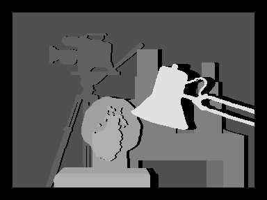
TSUKUBA stereo benchmark
TSUKUBA stereo benchmark tsukuba.zip can be downloaded from The Middlebury Computer Vision Pages , which is famous for computer vision benchmarks. Unpack tsukuba.zip to get
- scene1.row3.col1.ppm
- scene1.row3.col2.ppm
- scene1.row3.col3.ppm
- scene1.row3.col4.ppm
- scene1.row3.col5.ppm
- truedisp.row3.col3.pgm
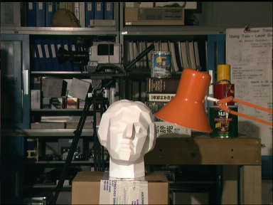
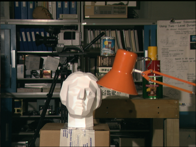
Parallax is too defined
The orange standlight is at the forefront, but the parallax is defined just to the right of the standlight in the true parallax image. The backmost bookshelf is visible just to the right of the standlight in the right image, but this part is hidden in the left image. Therefore, the original parallax should not be defined. The true parallax image is a rumor that it was made from a laser measured distance to the target in the right image, so it is certainly ground-truth, but as a parallax it cannot be used as it is.
Gaze and depth number
Therefore, instead of assigning disparity to the right pixel (pixel-disparity model), consider assigning a depth number to the gaze (gazeline-depth model).
By doing so, the positional relationship in the real space can be recognized more correctly, and the case where it is hidden and cannot be seen can be eliminated.
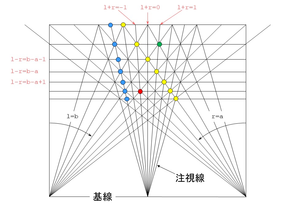
In the above figure, r and l are integer variables representing pixel positions, a is a negative integer constant, and b is a positive integer constant. r and l are 0 at the center of the image and the right direction is positive. Let r and l represent the left and right gazes that pass through the pixel. The intersection of left and right lines of sight where l + r = integer constant is on a straight line from the midpoint of the line connecting the left and right cameras (this is called the base line) to the far side. This line is called the gaze line (gaze_line). The intersection of left and right gazes where l-r = integer constant is on a straight line parallel to the base line. A number is assigned to this line from the far side to the front, and this is called the depth number (depth_number). If infinity is 0, the depth number is the same as the parallax. The yellow circle represents the pixel-disparity model, and the blue circle represents the gaze_line-depth model.
What is important here is that the number of gazes is twice the number of pixels. When the same pixel has a different parallax, it moves to the next gaze, but when the same parallax is different by one, it moves to the next gaze. If you pay attention to this, you can convert from pixel-disparity model to gazeline-depth model. Note that the resolution in the depth direction is halved when using the same number of gaze lines as the number of pixels. The program must also consider the scale factor.
Next, if the red circle and the green circle are obtained from the true parallax, this figure shows that the green circle is shaded and cannot be seen. I don't notice if I consider only the parallax of the right image, but I notice that I can't see the left side if I consider it equally. In addition, it can be seen that there is a relationship in which it is shaded when the depth change is larger than the gaze position change. This is a very important property because the depth changes only by 1 when moving to the next gaze. While the parallax can vary greatly between adjacent pixels, the depth changes only by a maximum of 1 between adjacent gazes. In article 3, the prohibition value comes out, which is to suppress the change in depth to a maximum of 1 between adjacent gazes.
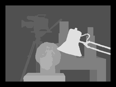
Corrected parallax image
The parallax image (true.png) corrected in this way is as follows.
Where the parallax cannot be defined (called occlusion), the value is 0 and the image is black.
Program distribution
The program true_disparity.cpp that corrects this was developed on Ubuntu16.04LTS. I use g ++ and OpenCV-3.0.0, but OpenCV only uses imread () and imwrite (), so I don't care about the version. To compile and run, just enter
make./true disparity_file_to_correct result_disparity_file scale_factor