12. Fundamental Matrix and Essential Matrix
Summary of stereo parallel processing
In article 10, when the rotation matrix indicating how much the right camera image is rotated with respect to the left camera image is \(R\) (ie, \(R_r=RR_l\)), the right image \(\tilde{\ddot{m_r}}\) and the left image \(\tilde{\ddot{m_l}}\) converted to \begin{align} \tilde{\ddot{m_r}}=A_rLA_r^{-1}\tilde{m_r} \label{eq:16} \end{align}\begin{align} \tilde{\ddot{m_l}}=A_rLRA_l^{-1}\tilde{m_l} \label{eq:15} \end{align} are Explain that the image taken by a camera and the same camera are images taken by moving in parallel in a certain direction, and the direction of the parallel movement can be set to any direction by selecting the rotation matrix \(L\). did. Also, in article 11, using graph cut by Gaze_line-Depth Model, \begin{align} L \end{align}\begin{align} LR \end{align} is calculated for two images to be images taken by a camera and the same camera moving in parallel in the \(-fu\) axis direction. I explained that I can do things (stereo parallelism). Here I would like to find the basic matrix \(F\) (Fundamental Matrix) and the basic matrix \(E\) (Essential Matrix) of these stereo cameras. OpenCV has findFundamentalMat function and findEssentialMat function to estimate \(F\) and \(E\) from multiple corresponding points, but with this new method, \(F\) and \(E\) are obtained from the correspondence as a 3D surface where all pixels match. In the conventional flow, \(F\) and \(E\) are required for stereo processing, but \(F\) and \(E\) are obtained after stereo processing is performed first. However, the camera matrix \(A\) must still be obtained by the Z. Zhang method. As will be described later, the correct basic matrix and basic matrix can be obtained if the camera matrix has a reasonable value.
Stereo camera \(F\) and \(E\)
In the stereo camera, the left image coordinate \(\tilde{m_l}\) and the right image coordinate \(\tilde{m_r}\) of the point \(P\) in the space are related (constrained) with the \begin{align} \tilde{m_l}^T F \tilde{m_r} = 0 \label{eq:5} \end{align} by the basic matrix \(F\) (Fundamental Matrix), and the left camera coordinate \(x_l\) and the right camera coordinate \(x_r\) are the basic matrix \(E\). Associated with \begin{align} x_l^T E x_r = 0 \label{eq:6} \end{align} by (Essential Matrix). \eqref{eq:5} is the basic equation, and \eqref{eq:6} is the basic equation. See the vision textbook to see why this is true. Since \(F\) and \(E\) are \begin{align} x_l^T E x_r = (A_l^{-1}\tilde{m_l})^T E A_r^{-1}\tilde{m_r} = \tilde{m_l}^T(A_l^{-1})^T E A_r^{-1}\tilde{m_r} = \tilde{m_l}^T F \tilde{m_r} ,\end{align} there is a relationship of \begin{align} F = (A_l^{-1})^T E A_r^{-1} .\end{align}
Basic matrix \(F\) for parallel stereo cameras
Then, in a stereo camera that has completed parallelization, \(v\) is common in the basic equation \begin{align} (\tilde{\ddot{m_l}})^TF\tilde{\ddot{m_l}}= \begin{pmatrix} u_l & v & 1 \end{pmatrix}F \begin{pmatrix} u_r \\ v \\ 1 \end{pmatrix}=0 ,\end{align} and \(u_l\) and \(u_r\) become whatever the depth of the point \(P\), so it must be \begin{align} \begin{pmatrix} u_l & v & 1 \end{pmatrix} \begin{pmatrix} 0 & 0 & 0 \\ 0 & 0 & s \\ 0 & -s & 0 \end{pmatrix} \begin{pmatrix} u_r \\ v \\ 1 \end{pmatrix}=0 .\end{align} That is, for \(\tilde{\ddot{m_l}}\) and \(\tilde{\ddot{m_l}}\), its base matrix \(f\) is \begin{align} f = \begin{pmatrix} 0 & 0 & 0 \\ 0 & 0 & s \\ 0 & -s & 0 \end{pmatrix} .\end{align} When this is returned to the original \(\tilde{m_l}\) and \(\tilde{m_r}\), it is \begin{align} (A_rLRA_l^{-1}\tilde{m_l})^T \begin{pmatrix} 0 & 0 & 0 \\ 0 & 0 & s \\ 0 & -s & 0 \end{pmatrix} A_rLA_r^{-1}\tilde{m_r}= (\tilde{m_l})^T(A_l^{-1})^TR^TL^TA_r^T \begin{pmatrix} 0 & 0 & 0 \\ 0 & 0 & s \\ 0 & -s & 0 \end{pmatrix} A_rLA_r^{-1}\tilde{m_r}=0 ,\end{align} so its base matrix \(F\) is \begin{align} F = (A_l^{-1})^TR^TL^TA_r^T \begin{pmatrix} 0 & 0 & 0 \\ 0 & 0 & s \\ 0 & -s & 0 \end{pmatrix} A_rLA_r^{-1} \end{align} or \begin{align} F = (A_l^{-1})^TR^TL^TA_r^TfA_rLA_r^{-1} \end{align} for \(\tilde{m_l}\) and \(\tilde{m_r}\).
Program distribution
Then, the program which calculates a basic matrix by stereo processing is explained. graph_cut.cu , rectify.cpp , makefile , 2_R.png , 2_L.png Please download. rectify.cpp adds the fundamental () function to rectify.cpp in article 11 and has a slightly improved startup format. Therefore, this rectify.cpp is the latest mainstream. The fundamental () function is now executed in the M key command (stereo parallelization (do calibration)). The types and number of single character key commands that can be used are the same as rectify.cpp in article 11. The startup format is
./rectify right_image left_image max_disparity min_disparity penalty inhibit divisor optionStart the program by entering
make rec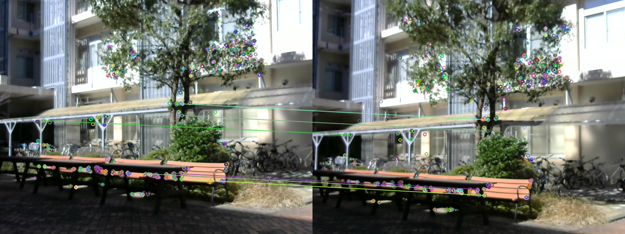

Contents of fundamental () function
First, find the basic matrix F at the beginning of the function. The input argument of the function is the component of the Rodriguez rotation vector of the left camera and the right camera determined by stereo parallelization processing by graph cut. M is the camera matrix. If the value of M is close to the true value, the result is hardly affected. For example, even if the focal length is several times different, there is no difference that can be seen. Of course, if the difference is 100 times, stereo parallelization using graph cut will not work. This seems to be important, but has not been examined in detail. So all camera matrices use the same M. In addition, since the camera matrix M has been used, it may be that the basic matrix is being obtained instead of the basic matrix at that time, but it is verified whether there is a corresponding point on the previous epipolar line. Is considered to be the verification of the fundamental matrix F. M.inv () is an inverse matrix and M.t () is a transposed matrix.
void fundamental(int l0, int l1, int l2, int r0, int r1, int r2) {
  cv::Mat lV = cv::Mat::zeros(1, 3, CV_64F);
  cv::Mat rV = cv::Mat::zeros(1, 3, CV_64F);
  lV.at(0, 0) = 0.00001*l0;
  lV.at(0, 1) = 0.00001*l1;
  lV.at(0, 2) = 0.00001*l2;
  rV.at(0, 0) = 0.00001*r0;
  rV.at(0, 1) = 0.00001*r1;
  rV.at(0, 2) = 0.00001*r2;
  cv::Mat lR;
  cv::Mat rR;
  Rodrigues(lV, lR);
  Rodrigues(rV, rR);
  cv::Mat f = cv::Mat::zeros(3, 3, CV_64F);
  f.at(1, 2) =  1.0;
  f.at(2, 1) = -1.0;
cv::Mat F = M.inv().t()*lR.t()*M.t()*f*M*rR*M.inv(); cv::Mat lcolor = lframe.clone();
cv::Mat rcolor = rframe.clone();
cv::Mat lgray;
cv::Mat rgray;
cv::cvtColor(lcolor, lgray, CV_BGR2GRAY);
cv::cvtColor(rcolor, rgray, CV_BGR2GRAY);
std::vector<cv::KeyPoint> lkeypoints;
std::vector<cv::KeyPoint> rkeypoints;
cv::Mat ldescriptor;
cv::Mat rdescriptor;
auto detector = cv::ORB::create();
detector->detectAndCompute(lgray, cv::Mat(), lkeypoints, ldescriptor);
detector->detectAndCompute(rgray, cv::Mat(), rkeypoints, rdescriptor); cv::BFMatcher matcher(cv::NORM_HAMMING, true);
std::vector<cv::DMatch> matches;
matcher.match(ldescriptor, rdescriptor, matches); std::vector<cv::DMatch> g_matches;
std::vector<cv::KeyPoint> g_lkeypoints;
std::vector<cv::KeyPoint> g_rkeypoints;
for (int t = 1; ; t++) {
int n = 0;
for (int i = 0; i < matches.size(); i++) if (matches[i].distance < t) n++;
if (n > 5) {
for (int i = 0; i < matches.size(); i++) {
if (matches[i].distance < t) {
g_matches.push_back(matches[i]);
g_lkeypoints.push_back(lkeypoints[matches[i].queryIdx]);
g_rkeypoints.push_back(rkeypoints[matches[i].trainIdx]);
}
}
break;
}
} cv::Mat image_matches;
drawMatches(lcolor, lkeypoints, rcolor, rkeypoints, g_matches, image_matches);
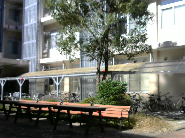
cv::imwrite("matches.png", image_matches); cv::Mat image_lkeypoints;
cv::Mat image_rkeypoints;
cv::drawKeypoints(lcolor, g_lkeypoints, image_lkeypoints, cv::Scalar(0, 0, 255));
cv::drawKeypoints(rcolor, g_rkeypoints, image_rkeypoints, cv::Scalar(0, 0, 255));
cv::imwrite("lkeypoints.png", image_lkeypoints);
cv::imwrite("rkeypoints.png", image_rkeypoints); std::vector<cv::Point2f> lkeypoints_2f;
std::vector<cv::Point2f> rkeypoints_2f;
cv::KeyPoint::convert(g_lkeypoints, lkeypoints_2f);
cv::KeyPoint::convert(g_rkeypoints, rkeypoints_2f);
std::vector<cv::Vec3f> llines;
std::vector<cv::Vec3f> rlines;
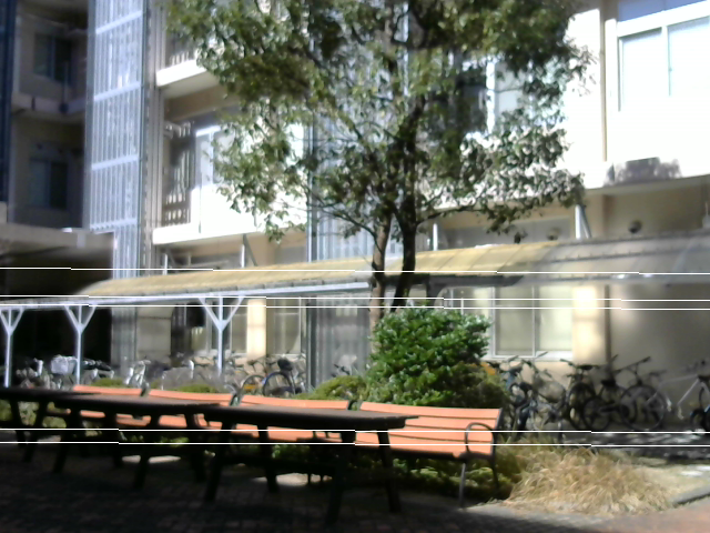
cv::computeCorrespondEpilines(rkeypoints_2f, 1, F, llines);
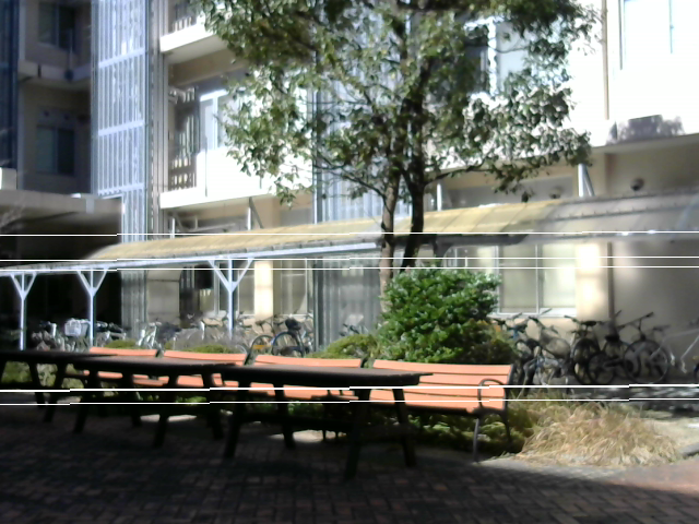
cv::computeCorrespondEpilines(lkeypoints_2f, 2, F, rlines); float a, b, c;
for (auto it = llines.begin(); it != llines.end(); it++) {
a = (*it)[0];
b = (*it)[1];
c = (*it)[2];
cv::line(lcolor, cv::Point(0, -c/b),
cv::Point(lcolor.cols-1, -(a/b*(lcolor.cols-1)+c/b)),
cv::Scalar::all(255));
}
for (auto it = rlines.begin(); it != rlines.end(); it++) {
a = (*it)[0];
b = (*it)[1];
c = (*it)[2];
cv::line(rcolor, cv::Point(0, -c/b),
cv::Point(rcolor.cols-1, -(a/b*(rcolor.cols-1)+c/b)),
cv::Scalar::all(255));
}
cv::imwrite("lepilines.png", lcolor);
cv::imwrite("repilines.png", rcolor);
}Impressions
This time, we used a feature point extractor called ORB (Oriented FAST and Rotated BRIEF) to check whether the basic matrix was obtained correctly, but the corresponding points from two images with different viewing positions and orientations Finding by processing and deducting the basic matrix deductively from it, as Ishidate Satoshi pointed out, even though the theory is correct, in the actual image I feel that errors and mistakes in the image handling part will be a big problem It was. So, what is to do by finding the basic matrix using the result of stereo parallelization processing using stereo processing, but the direction of rotation and translation between cameras is known at the stage when stereo parallelization processing is over Therefore, there is no point in obtaining the basic matrix or the basic matrix. I just confirmed that the stereo parallelization was done correctly. The basic matrix can define the relationship between the images without knowing the arrangement of the stereo cameras and each camera matrix, the contents can be determined from several corresponding points, and the stereo processing can be attacked from there Because it is significant, the stereo processing using the graph cut by Gaze_line-Depth Model introduced here is a surface extraction process in 3D space that does not use image processing (2D processing) at all, so another path was selected I think that.
Extracting camera internal parameters by Z. Zhang's method
Finally, there is a program that extracts the camera matrix and distortion coefficient. This is a program that uses the OpenCV library function cv :: calibrateCamera () that incorporates the Z.Zhang method. Basically, it is not different from the OpenCV example (calibration.cpp), but the OpenCV example was too difficult to read, so I made it to my liking. Download the following calib.cpp , calib_png.cpp , calib_cam.cpp , near.png , far.png , board_ng.png , board_ok.png , and circles.pdf .
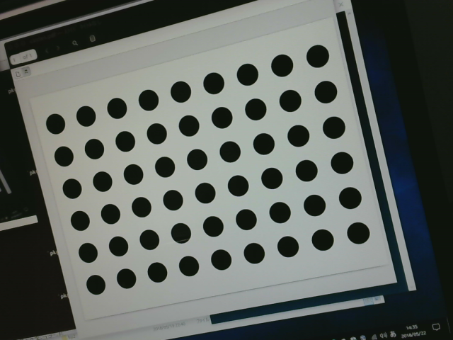
near.png is the nearer image of article 11, "Perspective calibration board (left is far, right is near)". far.png is the far image. board_ng.png is the same calibration board recently taken with Logitech C270. In this calibration board, paper with circles.pdf printed is pasted on the foamed polystyrene board, but nearly two years have passed since it was made, so there are wrinkles on the paper pasted compared to near.png It has stopped. I think the flatness of the foamed polystyrene board is quite good. board_ok.png is a recent photo taken with Logitech C270 with circles.pdf displayed on the display. Although board_ng.png does not know what is wrong with the eyes, the result is strange. The result seems to be more stable when the calibration pattern shown on the display is taken.
When
make near./calib_png nof_features_in_horizontal nof_features_in_vertical distance_between_features image_filemake farmake ng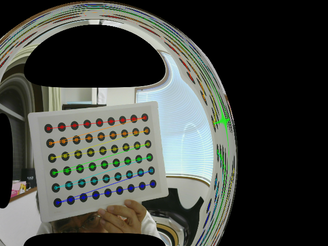
make okThis time, when
make camBriefly explain the program. calib_png.cpp and calib_cam.cpp have main (). calib.cpp is a collection of functions shared from calib_png.cpp and calib_cam.cpp.
calib () in calib.cpp calibrates a single camera from one or more images. First, it is checked whether there is a circles grid pattern (circles grid) in a given image, and if it is not found, it is checked whether a chessboard pattern exists. If this is not found, it returns false. The argument picture is how many images the given image is. When picture is 0, it means that the given image is the first image. In this case, calibration is performed with this single image. When picture is 3, it means that the given image is the fourth image. In this case, calibration is performed with 4 images. In this case, the information about the third image is stored in the argument points. These points are defined on the side that calls calib (), and information is accumulated each time calib () is called. points is a vector vector that contains the pixel positions of the feature points detected in the image. The upper vector corresponds to the number of images. On the other hand, Points defined in calib () are the coordinates of feature points of the calibration board to be detected. The z coordinates of feature points are all set to 0.0, and the feature points are assumed to be on the plane. It is an important premise of Z.Zhang's method that the feature points are on the plane. The space between feature points (real distance) is embedded in this point, but it only affects the movement information tvecs. This is because only the movement information tvecs is given at real distance. The rotation information rvecs represents the angle, so it is independent of pixel and actual distance. Other camera matrixes such as MM are values in pixels. Call OpenCV's calibrateCamera () with the points, points, and pixel size of the image as input information. The result is initially written to the camera matrix MM, distortion vector DD, rotation information rvecs, movement information tvecs, and reprojection error rms, which have no values at all. The option specification of how to execute calibrateCamera () enumerates all items and commented out. The image passed to calib () is added with the detected feature points and the feature points connected by lines.
Next, map12_make () in calib.cpp is a function that creates a conversion table (map1, map2) for use with OpenCV remap (). First, OpenCV's getOptimalNewCameraMatrix () is called to find a new camera matrix that includes all pixels in the image when distortion is corrected. Next, using OpenCV's initUndistortRectifyMap (), a conversion table that obtains an image from which distortion has been removed based on this new camera matrix is created from the original camera matrix and distortion vector. Since rotation is not necessary at this time, a rotation matrix that means no rotation is created from the Rodriguez zero rotation vector.
Next, map12_init () in calib.cpp is a function that creates a conversion table (map1, map2) for display. It is assumed that it will be rewritten to the correct value later.
Next, main () in calib_png.cpp calibrates a single camera with one image read from the file.
Next, main () of calib_cam.cpp enters a loop that displays the image from the camera in the window using the conversion table for the time being. This will display a video. The q key exits the loop. The d key reverts to the situation when you first entered the loop. Each time the c key is pressed, a single camera is calibrated with multiple images by adding the current image. The first c key is used for calibration with one image. For the time being, the conversion table is updated to the correct conversion table according to the calibration result. The s key outputs the current camera matrix and distortion vector to a file. The n key writes the image of the previous c key to a file named board_ng.png. The o key writes the image of the previous c key to a file named board_ok.png. The last two commands are used to examine images that are not displayed correctly or not.